Projects that either:
- are too old,
- are less academic and maybe just for fun,
- have unfortunately failed :(
- or simply don’t fit into any larger category.
Take a look at a curated (and more research-oriented) list here.
This page is far from complete (and so is this whole site, actually). I will
upload some pictures and add some description at some random moments I feel
pleased to (or have enough time to).
PCBA gallery 🎨
IEEE 1451 standard development (2018-2022)

(September 2018)
Corrigendum
The silkscreen designator “WiFi” in the lower right corner of the carrier
board is incorrect. That connector was for an nRF24
wireless module, which does operate at 2.4GHz but does not implement any
IEEE 802.11 technology.
Controller: EK-TM4C1294XL
of Texas Instruments

(October 2018)
Controller: STM32F103RCT6
of STMicroelectronics

(2019)
Ta-da! From now on, we’ve stepped into the era of Raspberry Pi.

(2020)
However, this joy didn’t last long: we felt increasingly frustrated by
complaints from those Pis about poor power supply, basically because most
micro-USB (for model 3B/3B+) chargers and cables are not exceptional enough to
feed these monsters.
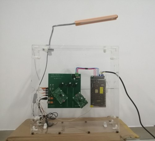
So we turned to some serious switching power supplies, with some really
exceptional specs like 5V 20A (!) or more. Check this picture
to get a sense of how conspicuous it looks compared to the prototype itself.
Note well, this also means we are bypassing the micro-USB port at all and
directly powering Raspberry Pis through their 40-pin headers.
As a result, the protection around the USB circuit is bypassed as well.
Remember to replicate it on your own design right before entering the headers,
if you do care about safety, and about these adorable Pis.
More information about this version can be found here
and here.

(2021)
This version kind of necromances many exciting bits of previous ones, like
microcontroller, battery, power monitor and so on. It also, of course, brings
even more fun.
The Noctua fan is connected to the carrier
board (via the standard interface
you may find on your PC’s motherboard) and is thus fully controllable!
Power analysis of Raspberry Pi (2020)

INA219
CCS'21 paper
A color identifier used in assembly line (2017)
NUEDC and its training (2017)
Advisor: Yan Yuan
Connectivity of SJTU’s private BitTorrent tracker 🍇
By the way, here’s my user bar:

Toy CI for my research group ⚙️